Interface
Interface elements can be regarded as a type of distributed spring element that models the mechanical behavior between adjacent elements. The element I2D4 is applicable to two-dimensional problems. Since interface elements are defined based on their geometric characteristics, they are not separately classified into plane stress or plane strain types. IAX4 is used for axisymmetric conditions, while I3D6 and I3D8 are applicable in three-dimensional analyses.
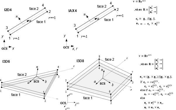
Fig. 4.10-1. Interface element
Example
*Material, Type=GapHook, Name=cont
 5E5, 0.1, 4E5, 0.2   # kg, g, kh, h

*Material, Type=UncoupledInterface, Name=inf
 100., 200., cont

*Section, Type=Interface, Name=infSection
 inf, 2

*Element, Type=I2D4
 1, 1, 2, 11, 12, S=infSection
*Element, Type=I2D4
2+2 two dimensional interface element
*Element, Type=I2D4, ELSet=elset
 id, n1, n2, n3, n4{, S=section}
 ...
Specifications
- No. of nodes: 4
- No. of integration pts.: At Gauss point
- Fields: ITR=[ITR.A ISF.N] IRD=[IRD.A IRD.N] at Gauss point.
- Compatible section: InterfaceSection
- Active DOFs: X, Y
*Element, Type=IAX4
2+2 axisymmetric interface element
*Element, Type=I2D4, ELSet=elset
 id, n1, n2, n3, n4{, S=section}
 ...
Specifications
- No. of nodes: 4
- No. of integration pts.: At Gauss point
- Fields: ITR=[ITR.A ISF.N] IRD=[IRD.A IRD.N] at Gauss point.
- Compatible section: InterfaceSection
- Active DOFs: X, Y
*Element, Type=I3D6
3+3 three dimensional interface element
*Element, Type=I3D6, ELSet=elset
 id, n1, n2, n3, n4, n5, n6{, S=section}
 ...
Specifications
- No. of nodes: 6
- No. of integration pts.: At Gauss point
- Fields: ITR=[ITR.A ITR.B ISF.N] IRD=[IRD.A IRD.B IRD.N] at Gauss point.
- Compatible section: InterfaceSection
- Active DOFs: X, Y, Z
*Element, Type=I3D8
4+4 three dimnesional linear quadratic interface element
*Element, Type=I3D8, ELSet=elset
 id, n1, n2, n3, n4, n5, n6, n7, n8{, S=section}
 ...
Specifications
- No. of nodes: 8
- No. of integration pts.: At Gauss point
- Fields: ITR=[ITR.A ITR.B ISF.N] IRD=[IRD.A IRD.B IRD.N] at Gauss point.
- Compatible section: InterfaceSection
- Active DOFs: X, Y, Z
*Section, Type=Interface
Define a section for interface element
*Section, Type=Interface, Name=name
 matA,matB,matN,thick,localUnitSystem

*Section, Type=Interface, Name=name
 cohesive_material,thick
Keyword line
- Name=name: section name(required).
First data line for uncoupled uniaxial materials
- matA, matB, matN: reference uniaxial material models (required). A, B, and N correspond two tangential directions and normal direction.
- thick: Trasverse thickness. Optional. default 1. Used in 2D interface element
- localUnitSystem: local UnitSystem with force-length form (optional).
First data line for cohesive material
- cohesive_material: Cohesive material model (required)
- thick: Trasverse thickness. Optional. default 1. Used in 2D interface element
If three materials are specified, independent traction–relative displacement relations are applied in each direction. In this case, the referenced materials shall support uniaxial material models only. For example, if the stress–strain relation of a uniaxial material model is used for the constitutive relation in the A-direction, it shall be interpreted as a traction–relative displacement relation. The optional localUnitSystem shall be specified in the form of force-length, such as kN-mm. The following rules shall apply.
- localUnitSystem is optional and shall be specified in the form of force-length, such as kN-mm. The force unit shall be one of N, kN, kgf, tonf, lbf, or kip, and the length unit shall be one of m, cm, mm, km, in, ft, yd, or mi.
- If localUnitSystem is specified,
*Environment, TYPE=UnitSystem(i.e., the global UnitSystem) shall be defined. - If localUnitSystem is not specified, the unit system shall follow the global UnitSystem defined by
*Environment, TYPE=UnitSystem. - localUnitSystem defines the unit system for matA, matB, matN, and thick.
- If localUnitSystem is identical to the global UnitSystem, matA, matB, and matN are used with a one-to-one conversion. Otherwise, an appropriate unit conversion shall be performed. For example, if the global UnitSystem is kN-m and the localUnitSystem is kN-mm, the relative displacement is internally converted from m to mm (×1000) before evaluating the material model, and the traction computed by the material model in kN/mm² is then converted back to the analysis unit system, kN/m², for use in the analysis.