Tutorial 01
Beam Cantilever
Goal
Use a realistic cantilever beam example to learn:
- node and beam-element layout
- material and section definition
- distributed load and support definition
- analysis execution
- basic result review
Why start with a beam model
A beam model is ideal for getting started because it describes the same structural behavior with the smallest modeling cost.
- small model size
- fast results
- clear interpretation of boundary conditions and loads
Tutorial case
This tutorial uses a linear-elastic reinforced-concrete cantilever that can represent a balcony beam or a short slab-supporting bracket.
- span:
2.4 m - section:
300 x 600 mmrectangular beam - support: one fully fixed end at the wall face
- load:
18 kN/mdownward line load, representing tributary slab dead plus service load - mesh:
8beam elements with typeB3D2H
This is still simple enough for a first tutorial, but it is more realistic than a pure textbook point-load example.
Working input file
Repository file: Example/Tutorials/tutorial-beam-cantilever.inp
*Material, Type=IsoElasticity, Name=Concrete
 30e9, 0.2, 0, 2500   # E, nu, alpha, density

*Section, Type=Beam, Name=RC300x600
*Cell, Type=Rectangle, Mat=Concrete
 0.30, 0.60, 0, 0

*Node, NSet=AllNodes
 1, 0.0, 0.0, 0.0
 2, 0.3, 0.0, 0.0
 3, 0.6, 0.0, 0.0
 4, 0.9, 0.0, 0.0
 5, 1.2, 0.0, 0.0
 6, 1.5, 0.0, 0.0
 7, 1.8, 0.0, 0.0
 8, 2.1, 0.0, 0.0
 9, 2.4, 0.0, 0.0

*Element, Type=B3D2H, ELSet=Cantilever
 1, 1, 2, S=RC300x600
 2, 2, 3, S=RC300x600
 3, 3, 4, S=RC300x600
 4, 4, 5, S=RC300x600
 5, 5, 6, S=RC300x600
 6, 6, 7, S=RC300x600
 7, 7, 8, S=RC300x600
 8, 8, 9, S=RC300x600

*NSet, Name=Tip
 9

*Constraint, Type=Support, Name=FixedEnd
 1, X|Y|Z|RX|RY|RZ

*Load, Type=LineDistributed, Name=DeckLoad
 Cantilever, GCS, 0, 0, -18000, 0, 0, 0

*Step, Type=Static, Name=Service
 Uniform, 0.1, 1
*Activate, Type=Element
 Cantilever
*Activate, Type=Constraint
 FixedEnd
*Activate, Type=Load
 DeckLoad
*Output
 D, FN, BSF
*Print, File=tutorial-beam-cantilever.prn
 D@Tip, FN@1, BSF@Cantilever
Modeling sequence
- create the nodes
- Node
- create the beam elements
- Beam Elements
- define the material
- Material
- define the section
- Modeling Convenience
- define constraints and loads
- Constraint
- Load
- define the analysis step
- Step
Run the analysis
You can save the .inp file and run hfAnalyzer, or import the same file into hfVisualizer.
Remote Control example:
hfVisualizer --remote import D:\Work\tutorial-beam-cantilever.inp --type Hyfeast
hfVisualizer --remote save D:\Work\tutorial-beam-cantilever.h5.hdb
hfVisualizer --remote run-analysis
Review the results
Check these first:
- whether the tip displacement points downward
- whether the fixed-end reaction balances the total distributed load
- whether the bending and shear-force output match the expected cantilever behavior
Postprocessing example:
hfVisualizer --remote post-step Service
hfVisualizer --remote post-frame 1
hfVisualizer --remote post-plot deformed on
hfVisualizer --remote post-scale deformed value 20
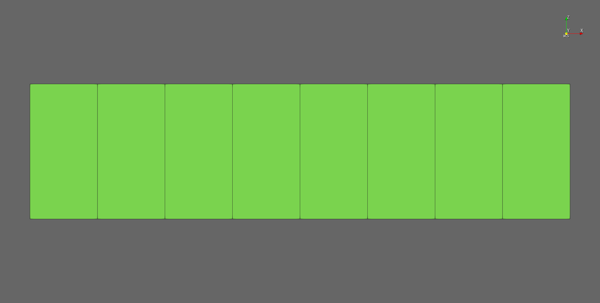
The following image shows the solved tutorial model with deformed shape display in hfVisualizer.
Main takeaway
- Beam models are fast and simple, but they do not directly show through-section stress distribution.
- If the goal is global behavior review, beam modeling is usually very efficient.
- For this tutorial case, the beam model is a good first pass before building a full 3D solid model.
Next step
- To solve the same problem with solids, continue with Tutorial 02 - Solid Cantilever
- To compare beam and solid choices, continue with Tutorial 03 - Beam vs Solid