Interface
경계면 요소는 요소간의 경계면의 역학적 거동을 표현하는 일종의 연속된 스프링 요소라고 할 수 있다. I2D4는 2차원에 적용가능한다. 경계면 요소는 기하학적 특성에 따라 결정되므로 평면응력, 평면변형으로 별도로 구분하지 않는다. IAX4는 축대칭, I3D6, I3D8은 3차원 조건에서 적용할 수 있다.
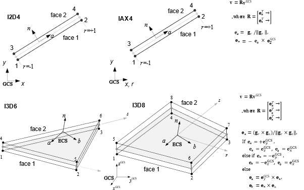
Fig. 4.10-1. Interface element
Example
*Material, Type=GapHook, Name=cont
 5E5, 0.1, 4E5, 0.2   # kg, g, kh, h

*Material, Type=UncoupledInterface, Name=inf
 100., 200., cont

*Section, Type=Interface, Name=infSection
 inf, 2

*Element, Type=I2D4
 1, 1, 2, 11, 12, S=infSection
*Element, Type=I2D4
2+2 two dimensional interface element
*Element, Type=I2D4, ELSet=elset
 id, n1, n2, n3, n4{, S=section}
 ...
Specifications
- No. of nodes: 4
- No. of integration pts.: At Gauss point
- Fields: ITR=[ITR.A ISF.N] IRD=[IRD.A IRD.N] at Gauss point.
- Compatible section: InterfaceSection
- Active DOFs: X, Y
*Element, Type=IAX4
2+2 axisymmetric interface element
*Element, Type=I2D4, ELSet=elset
 id, n1, n2, n3, n4{, S=section}
 ...
Specifications
- No. of nodes: 4
- No. of integration pts.: At Gauss point
- Fields: ITR=[ITR.A ISF.N] IRD=[IRD.A IRD.N] at Gauss point.
- Compatible section: InterfaceSection
- Active DOFs: X, Y
*Element, Type=I3D6
3+3 three dimensional interface element
*Element, Type=I3D6, ELSet=elset
 id, n1, n2, n3, n4, n5, n6{, S=section}
 ...
Specifications
- No. of nodes: 6
- No. of integration pts.: At Gauss point
- Fields: ITR=[ITR.A ITR.B ISF.N] IRD=[IRD.A IRD.B IRD.N] at Gauss point.
- Compatible section: InterfaceSection
- Active DOFs: X, Y, Z
*Element, Type=I3D8
4+4 three dimnesional linear quadratic interface element
*Element, Type=I3D8, ELSet=elset
 id, n1, n2, n3, n4, n5, n6, n7, n8{, S=section}
 ...
Specifications
- No. of nodes: 8
- No. of integration pts.: At Gauss point
- Fields: ITR=[ITR.A ITR.B ISF.N] IRD=[IRD.A IRD.B IRD.N] at Gauss point.
- Compatible section: InterfaceSection
- Active DOFs: X, Y, Z
*Section, Type=Interface
Interface 요소의 단면을 정의한다.
*Section, Type=Interface, Name=name
 matA,matB,matN,thick,localUnitSystem

*Section, Type=Interface, Name=name
 cohesive_material,thick
Keyword line
- Name=name: section name(required).
First dataline for uncoupled uniaxial materials
- matA, matB, matN: reference uniaxial material models (required). A, B, and N correspond two tangential directions and normal direction.
- thick: Trasverse thickness. Optional. default 1. Used in 2D interface element
- localUnitSystem: local UnitSystem with force-length form (optional).
First dataline for cohesive material
- cohesive_material: Cohesive material model (required)
- thick: Trasverse thickness. Optional. default 1. Used in 2D interface element
3개의 material을 지정하는 경우 각 방향별로 독립적인 표면응력(traction)-상대변위 관계를 적용한다. 이때 참조된 재료는 1축 재료모델을 지원하는 재료여야만 한다. 예를 들어 A방향 구성관계로 1축 재료모델의 응력-변형률 관계를 빌려 올 경우 표면응력-상대변위 관계로 취급한다. 옵션인 localUnitSystem은 kN-mm 등과 같이 force-length 형태로 지정한다. 다음의 규칙에 유의한다.
- localUnitSystem은 옵션이고 kN-mm등과 같이 force-length 형태로 지정한다. force에는 N, kN, kgf, tonf, lbf, kip 중 아니아고, length unit에는 m, cm, mm, km, in, ft, yd, mi 중 하나를 쓴다.
- localUnitSystem을 지정하는 경우에는
*Environment, TYPE=UnitSystem(즉, global UnitSystem)이 반드시 존재해야 한다. - localUnitSystem이 없는 경우 단위계는
*Environment, TYPE=UnitSystem에서 정의하는 global UnitSystem을 따른다. - locaUnitSystem은 matA,matB,matN,thick 단위계를 정의한다.
- locaUnitSystem과 global UnitSystem이 같으면 matA, matB, matN는 1:1 변환이다. 그렇지 않으면 적절한 변환이 이루어 진다. 예를 들어 global UnitSystem이 kN-m이고, localUnitSystem이 kN-mm이면, 상대변위는 내부적으로 m -> mm(×1000)로 변환해 재료모델을 평가하고, 재료모델에서 계산된 표면응력은 kN/mm² 단위 결과를 해석 단위계(kN/m²)로 다시 환산하여 사용한다.