18. HDB file structure
Overview
The HDB file(.hdb) is used for hfVisualizer, which contains both the model input section and analysis result values. The file format is available as text, binary, or HDF5.
- Text: Used for testing purposes and suitable for simple models(
.text.hdb) - Binary: A proprietary binary format(
.bin.hdb) - HDF5: Stored in HDF5 format(
.h5.hdb)
The HDB file structure mirrors that of the analysis input file (.inp), which consists of "Model" + "Analysis Step." However, it is distinct in that the "Analysis Step" stores analysis results over time.
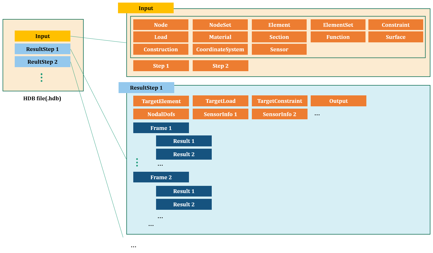
Fig. 18.1-1. HDB file structure
In an HDB file(.hdb), results for each analysis step are saved under a subcommand called *ResultStep. Each *ResultStep corresponds to a *Step in the analysis input file and stores individual analysis results. Subcommands like *Target, *FieldOutputs, *Frame, and *Result are available within it.
Example
...

*ResultStep, Name=step1
*TargetElements
 step1Elset
*TargetConstraints
 support
*TargetLaods
 load-DC
*Output
 D, SF, sensor1
*NodalDofs
 1002001, X|Y|Z|RX|RY|RZ         # nodeId, dofs
 1002002, X|Y|Z
 ...
*SensorInfo, Sensor=sensor1
 1, 1011023          # sensorPointId, elementId
 ...
*Frame,STime=0,RTime=0,LF=0
*Result, Field=D
 1002001, 0, 0, 0, 0, 0, 0       # nodeId, v1, v2, ...
 1002002, 0, 0, 0
 ...
*Result, Field=SF
 1 0. 0. 0. 0. 0. 0.             # elementId, v1, v2, ...
 2 0. 10. 1. 0. 1. 0.
 ...
*Result, Field=sensor1
 1, 0, 0, 0, 0                    # pointId, dx, dy, dz, value
 ...
*Frame,STime=0.1,RTime=0,LF=0
*Result, Field=D
 1002001, 1, 0, 1, 0, 0, 0
 1002002, 0, 2, 1
 ...
*Result, Field=SF
 1 0. 0. 0. 0. 0. 0.
 2 0. 10. 1. 0. 1. 0.
 ...
*Result, Field=sensor1
 1, 0.001, 0, 0, 1.2                   # pointId, dx, dy, dz, value
 ...
*ResultStep, Name=step2
...

*ResultStep, Name=step3
...
The *Step command defines an analysis step and includes subcommands such as *TargetElements, *TargetConstraints, *TargetLoads, *Output, *NodalDofs, *Frame, and *Result.
*ResultStep
Defines an ResultStep.
*ResultStep Name=name
Keyword line
- name : Name
*TargetElements
Specifies the elements targeted by the ResultStep. Here, elements refer to the output target, not necessarily the elements used in the analysis.
*TargetElements
 elset1, elset2, ...
First dataline
- elset1, elset2, ...: target elsets
*TargetConstraints
Specifies the constraints targeted by the ResultStep. Here, constraints refer to the output target, not necessarily the constraints used in the analysis.
*TargetConstraints
 constraint1, constraint2, ...
First dataline
- constraint1, constraint2, ...: target constraints
*TargetLoads
Specifies the loads targeted by the ResultStep.
*TargetLoads
 load1, load2, ...
First dataline
- load1, load2, ... : target loads
*Output
Indicates the output results included in the ResultStep.
*Output
 field|sensorName,...
 ...
First dataline and subsequent datalines
- field, ... : Name of field
- sensorName: Name of the output sensor
This is similar to the *Output in *Step, but it supports specifying secondary fields such as SF.3, S.11, S.Mises.
*NodalDofs
Outputs the degree of freedom pattern for used nodes.
*NodalDofs
 id, dofs
 ...
First dataline and subsequent datalines
- id, dofs: Node number and its degree of freedom pattern
This is only provided if nodal fields such as D, V, A are requested in *Output. It is not provided if a scalar nodal field like D.X is requested.
*Frame
Defines a frame in ResultStep.
*Frame, STime=stime, RTime=rtime, LF=lf
*Result, ...
...
*Result, ...
...
Keyword line
- stime: step time
- rtime: real time
- lf: load factor
In frequency analysis, stime represents the natural frequency. The subcommand *Result is available.
*Result
Outputs analysis results within a frame.
*Result, Name=name
 id,...
 ...
Keyword line
- name : Field name or sensor name
First dataline and subsequent datalines for nodal or elemental field
- id, .... : Node or element number and associated field values.
First dataline and subsequent datalines for sensor
- sensorPointId, dispX, dispY, dispZ, sensorValue: Sensor point ID, displacements (X, Y, Z), and the sensor value at that point.