MCK
You can define a 2-noded spring/damper element using the Spring element type, a 1-noded spring/damper element using the EarthSpring type, and a 1-noded concentrated mass using the PointMass type. These elements can have spring/damper properties or concentrated mass defined in any of the X, Y, Z, RX, RY, and RZ directions, as needed. All of these elements use the MCK section type, and each one can have its own material properties including a local coordinate system defined with *CoordinateSystem, TYPE=Orientation, and a scaling factor.
In the following example:
- Spring element 1001 has a spring constant of 10 in the X direction and 20 in the Y direction.
- Element 1002 adjusts the spring constants to 5 and 10 in the X and Y directions, respectively, by applying a scaling factor of 0.5.
- Element 1003 specifies a separate element coordinate system. If the element coordinate system is not specified, the Global Coordinate System (GCS) is used by default.
Example
*Section, Type=Spring, Name=springSection
 Spring, X, 10
 Spring, Y, 20.

*CoordinateSystem, TYPE=UCS, Name=springCS
 0,1,0, -1, 0, 0

*Element, Type=Spring, ELSet=sp
 1001, 1001, 1002, S=springSection
 1002, 1001, 1002, S=springSection, SF=0.5
 1003, 1002, 1003, S=springSection, CS=springCS
Example
*Node
 1001, 0,0,0

*Element, Type=PointMass, ELSet=pm
 1001, 1001

*Section, Type=MCK, Name=pmSec
 Mass, 100., 10., 10. 10 , # m, Ix, Iy, Iz, rx, ry, rz

*Distribution, TYPE=Section
 pm, pmSec
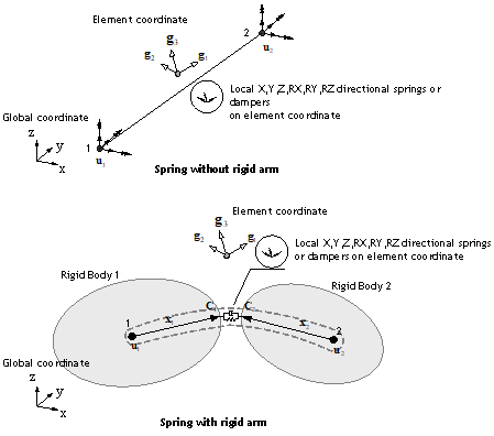
Fig. 4.11-1. Spring and Damper Elements
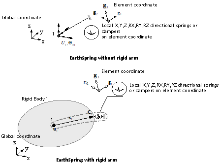
Fig. 4.11-2. EarthSpring Element
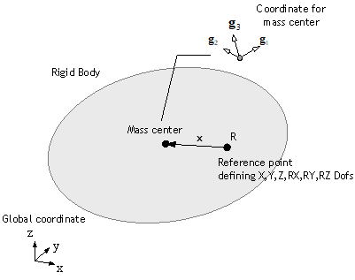
Fig. 4.11-3. PointMass Element
Sign Convention
For Spring and EarthSpring elements, the formulation is independent of the nodal coordinates of the connected nodes, so care must be taken in interpreting the signs of forces and deformations. Forces and deformations are determined based on the element's local coordinate system (ECS). If the ECS is not specified, it is the same as the global coordinate system (GCS). The following summarizes the sign convention for spring and damper elements.
(1) Spring Element
If no separate local coordinate system is defined (i.e., the local coordinate system is the same as the global coordinate system) and there is no rigid arm, the deformation is defined as the displacement difference between the end node and the start node (\(\delta = u_2 - u_1\)). For example, in a Spring element with a single spring in the X direction, the deformation is given as follows:
A positive value of \(\small\Delta U\) does not indicate tension but rather that the deformation at the end node is greater than at the start node. The sign of the force is interpreted similarly, and the same sign convention applies to the Damper element. Fig. 4.11-4 illustrates the sign convention for the Spring element. For a tension spring, a positive sign for both force and deformation indicates tension, and for a compression spring, a positive sign indicates compression.
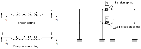
Fig. 4.11-4. Sign Convention for a Spring Element Without a Specified Local Coordinate System
If a separate local coordinate system is defined, the deformation is based on the local coordinate system.
For the EarthSpring element, if no separate local coordinate system is defined (i.e., the local coordinate system is the same as the global coordinate system) and there is no rigid arm, the deformation is defined as the displacement of the given node (\(\delta = u_1\)). For example, in an EarthSpring element with a single spring in the X direction, the deformation is given as follows:
In this case, a positive value of \(\small\Delta U\) does not indicate tension but rather that the connected node displacement is negative. The sign of the force is interpreted similarly. The same sign convention applies to the EarthDamper. Fig. 4.11-5 illustrates the sign convention for the EarthSpring element. For a tension spring, a positive sign for both force and deformation indicates tension, and for a compression spring, a positive sign indicates compression.
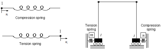
Fig. 4.11-5. Sign Convention for an EarthSpring Element Without a Specified Local Coordinate System
If a separate local coordinate system is defined, the deformation is based on the local coordinate system.
*Element, Type=Spring
*Element, Type=Spring, ELSet=elset
 id, n1, n2{, S=section, CS=cs, SF=sf}
 ...
Specifications
- No. of nodes: 2
- No. of integration pts.: 1
- Fields: SF=[...], SE=[...], DF=[...], DE=[...] at element center.
- Compatible section: MCK
- Active DOFs: Combination of X, Y, Z, RX, RY, RZ
- CS: ECS with the type of
*CoordinateSystem, TYPE=Orientation - SF: Scaling factor
SF refers to Spring Force, SE refers to Spring Deformation, DF refers to Damping Force, and DE refers to Damping Deformation Rate. The components are determined based on the active degrees of freedom. For example, for a spring using the Y and Z degrees of freedom, they are recorded in the order: SF=[SF.Y, SF.Z], SE=[SE.Y, SE.Z], and so on.
*Element, Type=EarthSpring
*Element, Type=Spring, ELSet=elset
 id, n1{, S=section, CS=cs, SF=sf}
 ...
Specifications
- No. of nodes: 1
- No. of integration points: 1
- Fields: SF=[...], SE=[...], DF=[...], DE=[...] at the element center.
- Compatible section: MCK
- Active DOFs: Combination of X, Y, Z, RX, RY, RZ
- CS: ECS with the type of
*CoordinateSystem, TYPE=Orientation - SF: Scaling factor
Refer to *Element, TYPE=Spring for explanations of SF, SE, DF,
*Element, Type=PointMass
Defines the cross-section for a concentrated mass element.
*Element, Type=PointMass, ELSet=elset
 id, n1{, S=section, CS=cs, SF=sf}
 ...
Specifications
- No. of nodes: 1
- No. of integration pts.: None
- Fields: None
- Compatible section: MCK
- Active DOFs: Combination of X, Y, Z, RX, RY, RZ
- CS: ECS with the type of
*CoordinateSystem, TYPE=Orientation - SF: Scaling factor
*Section, Type=MCK
Defines the cross-section for MCK elements such as Spring, EarthSpring, and PointMass.
*Section, Type=MCK, Name=name
 Spring, oneDof, k, km
 ...
 Damper, oneDof, c, cm
 ...
 Mass, m,Ix,Iy,Iz
 ...
 xRigid1,yRigid1,zRigid1, xRigid2,yRigid2,zRigid2,
First and subsequent dataline if necessary
- oneDof: Degree of freedom to which the spring/damper is applied, one of X, Y, Z, RX, RY, or RZ.
- k, km: Spring coefficient and model for the specified degree of freedom;
kmis optional. - c, cm: Damping coefficient and model for the specified degree of freedom;
cmis optional. - m, Ix, Iy, Iz: Mass (required) and rotational inertia (optional, default 0, 0, 0).
Last dataline if necessary
- xRigid1,yRigid1,zRigid1: position vector from ref. node (rigid arm vector) (optional, default 0,0,0)
- xRigid2,yRigid2,zRigid2: position vector from ref. node (rigid arm vector) (optional, default 0,0,0)
Example
*Section, Type=MCK, Name=springSection
 Spring, X, 10
 Spring, Y, 20.
 Damper, X, 5
 0,1,0, 0,2,0

*Section, Type=MCK, Name=springSection
 Mass, 100
 0,1,0, 0,2,0