Truss
The truss element can be considered a beam element that transmits only axial forces. Only the 3D 2-node truss element, T3D2, is supported. The following is a comparison with beam elements:
- The truss element transmits only axial forces and has only translational DOFs without rotational DOFs at the nodes.
- Variable cross-sections can be specified, similar to beam elements.
- The ECS can be defined and is used to determine the direction when applying loads, but it is not related to the stiffness matrix calculation within the element.
- EndRelease and Offset are ignored.
- Elemental loads in directions other than the axial direction are distributed to both end nodes according to the distance but do not cause deformation.
- Unlike beam elements, it cannot be used as a host element for Tendon.
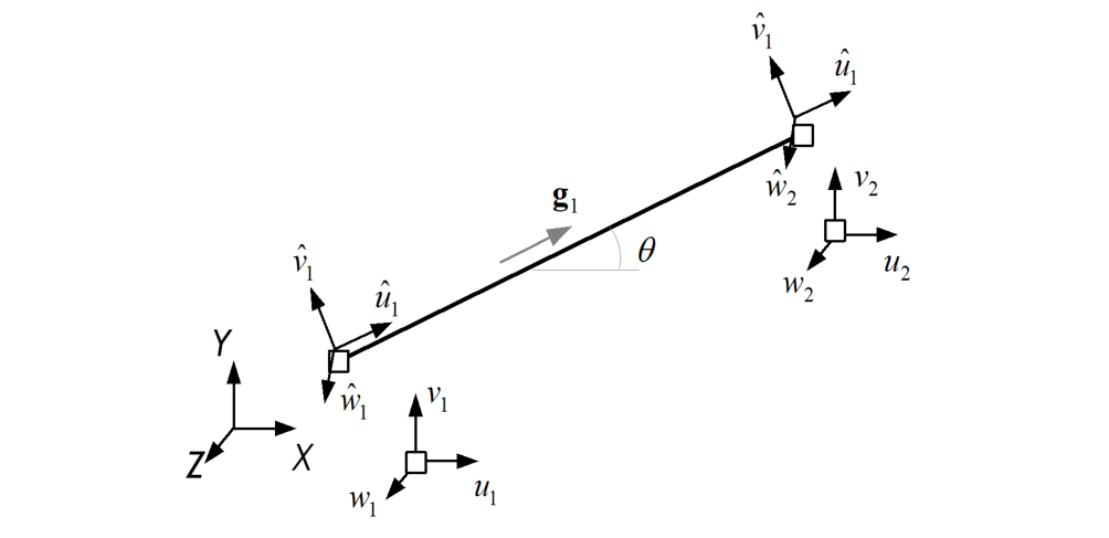
Fig. 4.3-1. Truss element
Example
*Element, Type=T3D2, ELSet=ALL
 1001, 1001, 1002

*Material, Type=IsoElasticity, Name=steel
 200., 0.2

*Section, Type=Beam, Name=truss
*Cell, TYPE=Value, Mat=steel
 0.1

*Distribution, TYPE=Section
 ALL, truss
*Element, Type=T3D2
*Element, Type=T3D2, ELSet=elset
 id, n1, n2, S=section
 ...
Specifications
- No. of nodes: 2
- No. of gauss points: 4 (Gauss-Lobatto rule used)
- Fields: BSF=[Nx], BSE=[Ex], BST=[T0] at Gauss point, Uniaxial model response at each layer of Gauss point
- Compatible section: Beam
- Active DOFs: X,Y,Z